Despite the announcement yesterday that Sheffield is the happiest city in the UK, I still haven’t quite got the better of my positive emotions. It’s hard to pick out the good points from the last couple of weeks, especially after eating the worst dinner since I became a middle-class, well-educated, free-thinking adult (honey on toast, soya mince with barbecue sauce, olives and jelly babies). That said, I have made *some* progress, and I’m still managing to make it into work before 10am every day, so it can’t be too bad.
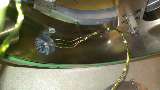
Since my last post about the problems with ULTRASPEC, it’s been “fixed” and broken again another two times. Being taken apart by the team at ATC in Edinburgh turned out to be quite a positive event for the whole project. The engineers discovered immediately after opening the lid what the original problem was – the tiny cables which operate the heater inside the cryostat had melted because the current running through them was too high. This caused a short circuit between the wires which measure the temperatures, so the nonsensical temperature readings I mentioned before were just that: rubbish.
This in itself was a relatively easy fix (they simply replaced the wires with stronger, higher grade ones, and re-programmed the heater controller to chill out a bit), but it’s far better that this happened here and now, and not in 6 months time when the whole thing is all set up and ready to go in Thailand. In addition, they found that the chip was actually seated 0.5mm lower than originally thought – meaning all the lens designs would have been calculated incorrectly. Though 0.5mm doesn’t seem like very much, it would totally screw up the image quality of the camera. So they fixed that too, put it all back together, and sent it back down to Sheffield. Overall, quite a productive visit then…
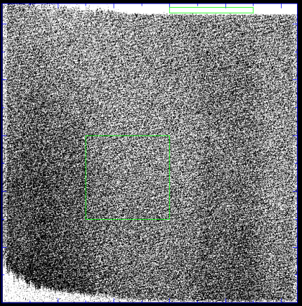
Or so we though. We got it all set up again, with the vacuum pumped and the cryostat cooled, by Friday afternoon. It was at this point that we discovered a new and entirely different problem. We found that the chip was measuring very high dark current (thermally excited electrons within the chip which are *not* caused by light). We also saw a bizarre structure in the images, which looked like another problem with the electronics, as well as the dark current issue.

Strange structure on the left side of the image, suggesting a serious problem with the read-out electronics.
The strange structure appeared to be that pixels in the lower left corner of the image were magically replaced in the top left corner, or that entire columns seemed to be shifted upwards by varying amounts. This somehow managed to make it look like there were counts/charges in the overscan area on the top of the chip (the white section in the top right of the image above). These overscan pixels don’t actually exist – they are imaginary pixels whose count levels should never vary, so finding definite values of charge in them is very worrying. Unfortunately I spent several hours every day of the bank holiday weekend unsuccessfully trying to fix this, with limited support from my supervisor, who was busy running a marathon, in Edinburgh of all places!
After many worried phone calls between my supervisor and the engineers in Edinburgh, we decide to open up the cryostat here and see if we could find any obvious problems. My supervisor was confident that there was a issue with the thermal connection between the cold liquid nitrogen tank and the chip, so this is what we really wanted to check. We took everything into a special clean room, donned real science-y overalls, boots and gloves, and had a look.
Actually, we did find that the thermal contact between the chip and the cold tank was on the dodgy side of ‘precarious’, but there was nothing evidently wrong with the cabling or electronics. We fixed the thermal contact and put it all back together. After another day of vacuum pumping and cooling, we tested the dark current and … found it to be unbelievably low. In addition the weird pattern had totally disappeared. In fact, after proper cooling and time to settle down, the dark current was reduced to zero, hurray! I was convinced this was too good to be true.
Indeed, it was. This time I really have no idea what’s happening, but after trying to test the responsiveness to light, we discovered the chip was still going absolutely bananas. Lots of nasty vertical stripes had appeared, and refused to leave. Even when allowing ample light to fall on to the chip it was only measuring it on a horizontal strip at the bottom, then sending these weird stripes all the way up the image. I don’t have a picture of this unfortunately, but basically the entire thing is still totally screwed. We’ll be opening it up again tomorrow to try to test the cabling, but it doesn’t look good. If we can’t fix it, it’ll be back up to Edinburgh again…Bah!
Not much other news at the moment. I wasted two days fighting with the formatting of my references for writing up. I finished most of my report on the testing so far, though I’m sure it will need a lot more work before it’s up to the right standard. I’ve also been working a bit with data from the robotic pt5m. This took several days to get anywhere with, but I’ve now managed to modify a Python script from my supervisor(s) which automatically plots a light curve for the data, and measures the magnitudes in each filter too, which is pretty neat! Sadly there’s no exciting science to come out of that yet, but hopefully there will be eventually.
Now it’s time for ice cream. Byee!


Sounds like fun 😛
A modified Python script? Nobody expects the ULTRASPEC Inquisition!
Fetch… THE COMFY CHAIR!